Magnetic Levitation (two coils)#
- Tags
Tracking, Unstable
- Available
1
- Inputs
2
- Outputs
3
Introduction#
The Magnetic Levitation setup consists of two vertical coils and a magnetic ball placed between the coils. The objective is to levitate the ball and control its position by manipulating the current through the coil. The figure below shows the system, including a schematic with the relevant variables.

Fig. 1 Magnetic Levitation setup.#
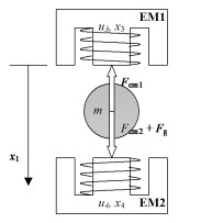
Fig. 2 Schematic of Magnetic Levitation with two coils.#
This system has two control inputs \(u_1\) and \(u_2\), which are the voltages applied to the coils. These inputs are commanded from the computer and are scaled between 0 and 1. There are three measured outputs: \(x_1\) – the position of the ball in meters, \(x_3\) and \(x_3\) – the currents through the top and the bottom coil, respectively. The speed of the ball, \(x_2\), can be calculated using position measurements.
Control Objective#
Design a controller that makes the ball position follow a specified reference trajectory. The controlled system should have zero steady-state error and adequate disturbance rejection properties, i.e., it should be able to recover from a small tick against the ball.
Simulink Template#
A Simulink template maglev.slx contains the necessary real-time interface blocks and some scopes. The file maglev_initialPD.m contains an initial PD controller to help with first experiments. Make your own copy of this file (and other files in the same directory) and use it as a starting point for your experiments.