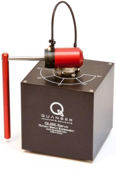
Qube/Rotary Pendulum#
- Tags
Low damping, Tracking, Unstable
- Available
4
- Inputs
1
- Outputs
2
Introduction#
The rotary pendulum system is a two-link rigid manipulator, also known as Furuta arm, operating in a 3D space. The horizontal link, called rotary arm rod, is actuated by a torque introduced by a DC motor acting on the rear end (joint) of the link. The vertical link, called pendulum link, is free to rotate the full \(360\) degrees. The goal is to control the motor such that the joints are stabilized at some desired angles. The easiest task is to stabilize the system around one of its stable equilibrium configurations. A more challenging task is when the second link is at its unstable equilibrium point. In the following figure, the Qube-Servo setup is shown at the left side and the relevant parameters and variables are depicted at the right.
|
|---|
Qube/Rotary pendulum setup. |
The control input \(u\) is the voltage applied on the DC motor that actuates the rotary arm rod. The scaled input signal ranges from \(-1\) to \(1\) (corresponding to the maximal clockwise and counter-clockwise torques, respectively) and can be commanded from the PC. There are two output measurements available: i) \(\theta\), the angle of the rotary arm and ii) \(\alpha\), the angle of the pendulum. The angles are measured in radians relative to the angles as they are when you initiate your experiment. You are encouraged to validate the sensor calibration that is inserted in the template Simulink block. The parameters of the system are given in Table \ref{tab:parameters}. Note that these values are approximate and not necessarily correct for your specific setup. Hence, you need to design an identification experiment to accurately identify the system’s parameters.
Control Objectives#
Design a controller that makes the angle of the rotary arm \(\theta\) follow a specified reference trajectory while stabilizing the pendulum link in the upright position. For simplicity, start with a stable equilibrium configuration and design a controller that damps out the swing. The eventual design should result into a zero steady-state error in \(\theta\) (small oscillations around the reference are permitted) and into an acceptable disturbance rejection properties, i.e., the ability to recover from a small tick against the link.
Simulink Template#
A Simulink template qubetemplate.slx contains the necessary real-time interface blocks and some scopes. Make your own copy of this file and use it as a starting point for your experiments. Before starting the first simulation, define the sampling period \(h\) as a variable in the workspace of Matlab.

