Inverted Pendulum#
- Tags
Rotational, Tracking, Unstable
- Available
1
- Inputs
1
- Outputs
2
Introduction#
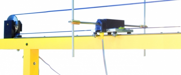
The inverted pendulum setup consists of a cart driven by a DC motor. The motor can steer the cart left and right on a track approximately one meter long. On the cart, a pendulum is mounted such that it can freely rotate around an axis that is perpendicular to the direction of motion of the cart. The objective is to control the motion of the cart such that the pendulum is balanced in its upright position. The schematic diagram the image below shows the construction of the system including all the relevant parameters and variables. Positive directions of variables are indicated by arrows.
|
|---|
Inverted pendulum setup. |
This system has one control input \(u\), which is the voltage driving the cart motor. This input is commanded from the computer and is scaled between -1 (corresponds to the maximal input moving the cart to the left) and +1 (corresponds to the maximal input moving the cart to the right). There are two measured outputs: \(d\) – the displacement of the cart from the track center, and \(\alpha\) – the angle of the pendulum. You will need to calibrate those measurements to correspond to their physical units, e.g., meters and radians, respectively.
Control Objective#
Design a controller that makes the cart follow a specified reference trajectory for \(d\) while balancing the pendulum. The controlled system should have zero steady state error in \(d\) and adequate disturbance rejection properties, i.e., it should be able to recover from a small tick against the pendulum.
Simulink Template#
A Simulink template that contains the neccesary real-time interface can be obtained by running the command P1_Main in the Matlab Command Window. From the dialog, double-click the button Pendulum 1 Device Drivers, and save the file to a local folder. You can start an experiment by going to the Hardware-tab, then clicking Build for Monitoring (wait a bit for the process to complete) and Connect below the play-button that reads Monitor to Tune.

