Reaction Wheel Pendulum#
- Tags
Rotational, Tracking, Unstable
- Available
1
- Inputs
1
- Outputs
2
Introduction#
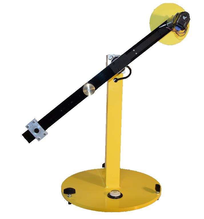
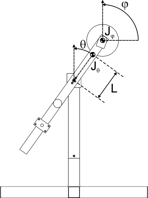
The rotational pendulum is an inverted pendulum type setup. To swing up and stabilise the system in an upright position DC motor drives a reaction wheel (a type of flywheel) forward and backward. The figures show photograph of the setup to which this description applies and a schematic drawing with the relevant parameters and variables. Positive directions of variables are indicated by arrows.
|
|---|
Reaction Pendulum setup. |
|
|---|
Schematic of the Reaction Pendulum setup. |
This system has one control input \(u\), which is the motor current. There are two measured outputs: \(\theta\) – the pendulum angle (5000 imp/rpm quadrature) and \(\varphi\) – the flywheel angle (1024 imp/rpm quadrature). You may need to calibrate those measurements to correspond to their physical units, e.g., radians.
The physical parameters of the system are listed in \tabref{parameters}. Note that these are approximate values and may not be entirely correct for your specific setup. Keep this in mind when designing identification experiments and methods.
Control Objective#
Design a controller that stabilizing the pendulum in the upright position (when the adjustable counterweight is in a position that makes the system instable). The controlled system should have zero steady state error in and adequate disturbance rejection properties, i.e., it should be able to recover from a small tick against the link. As this system does not allow for reference tracking, you need to design a swing-up controller instead.
Simulink Template#
A Simulink template contains the necessary real-time interface blocks and some scopes. Make your own copy of this file and use it as a starting point for your experiments. Before starting the first simulation, define the sampling period \(h\) as a variable in the workspace of Matlab.


