Tanks#
- Tags
Tracking, Stable,
- Available
1
- Inputs
4
- Outputs
3
Introduction#
The Tanks setup consists of three tanks arranged in a cascade. The objective is to keep the level in all three tanks at the desired value by adjusting the pump going into the first tank and three automatic valves. The figure below shows the system, including a schematic with the relevant variables.
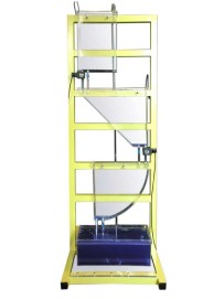
Fig. 3 Tanks setup.#
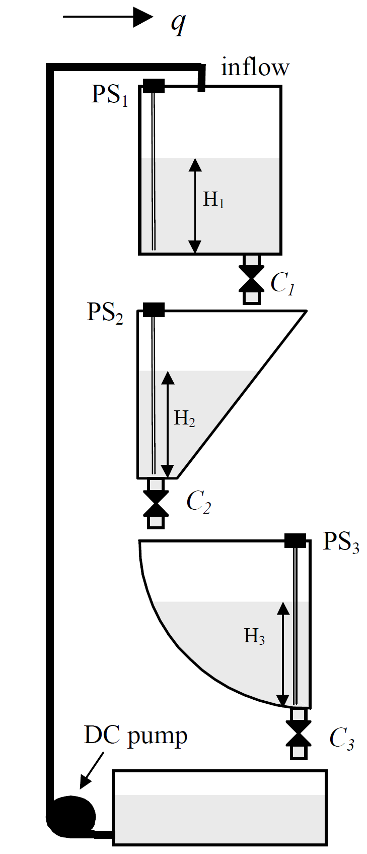
Fig. 4 Schematic of the three tanks.#
This system has three control inputs \(u_0\) and \(u_1\), \(u_2\), \(u_3\), which are the PWM signal to the pump and the opening of the three valves, respectively. These inputs are commanded from the computer. There are three measured outputs corresponding to the levels in the three tanks, \(H_1\), \(H_2\), \(H_3\).
Control Objective#
Design a controller that keeps the desired levels in all three tanks. The controlled system should have adequate disturbance rejection properties, i.e., it should be able to recover from adjusting the manual valves.
Simulink Template#
A Simulink template tanks_template.slx contains the necessary real-time interface blocks and some scopes. Make your own copy of this file (and other files in the same directory) and use it as a starting point for your experiments.