Ball and Beam#
- Tags
Rotational, Tracking, Translational, Unstable, Double integrator(s)
- Available
1
- Inputs
1
- Outputs
2
Introduction#
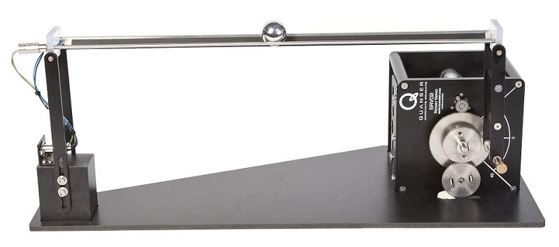
The ball and beam setup consists of a beam actuated by a motor and a ball. The motor can change the angle of the beam. The ball is rolling on the beam. The objective is to control the motion of the beam to postion the ball.
This system has one control input, which is the voltage applied to the driving motor. This input is commanded from the computer and saturated to -10 and +10.
There are two measured outputs:
the displacement of the ball relative to the center of the beam, and
the angle of the motor.
You will need to calibrate those measurements to correspond to their physical units, e.g., meters/millimeters and radians, respectively. For this purpose you can change the content of the blocks ‘Sensor offsets’ and ‘Sensor gains’ that are present in the template block diagram.
|
|---|
Ball and Beam setup. |
Video demonstration
Control objectives#
Broadly speaking, the control objective is to:
have the ball stabilized at a fixed position, while being able to reject small disturbances applied to the motor input (virtual disturbance), or manually applied to the ball. This while minimizing characteristics such as control input amplitude/energy, damping ratio (number of oscillations), etc.;
have the ball follow specified trajectories, especially (block-, triangular- or sinusoidal-) wave functions, while optimizing for time-domain or frequency domain specifications.
Parameters#
|
|---|
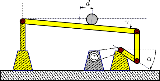
Schematic diagram of the Ball and Beam setup. |
Some physical parameters of the system are listed in the table below. Most of the values can easily be determined by measuring the dimensions and masses.
Symbol |
Parameter |
Value |
|---|---|---|
\(l_b\) |
beam length |
42.55 cm |
\(l_l\) |
lever arm length |
12 cm |
\(l_s\) |
support arm length |
16 cm |
\(r_b\) |
ball radius |
1.27 cm |
\(m_b\) |
ball mass |
0.064 kg |


